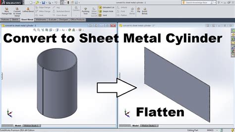
how to convert normal part to sheet metal To convert a solid part to a sheet metal part: Create the solid part. Click Convert to Sheet Metal (Sheet Metal toolbar) or Insert > Sheet Metal > Convert To Sheet Metal . Select Use gauge table. In Select Table , select a gauge table to use, or click Browse and browse to a gauge table. $823.99
0 · solidworks convert to sheet metal
1 · solid work to sheet metal converter
2 · solid work to sheet metal
3 · solid to sheet metal worksheets
4 · solid to sheet metal conversion
5 · convert solid to sheet metal youtube
6 · convert solid to sheet metal worksheet
7 · convert solid part to sheet metal
You must turn left at the junction ahead. You must not turn right, go straight .
To convert a solid part to a sheet metal part: Create the solid part. Click Convert to Sheet Metal (Sheet Metal toolbar) or Insert > Sheet Metal > Convert To Sheet Metal . Select Use gauge table. In Select Table , select a gauge table to use, or click Browse and browse to a gauge table.
https://www.youtube.com/channel/UCjd_zIvYtQymk0dPx3vTJcA/joinYou Can Support our Channel for more tutorials, We Provide SolidWorks, . By converting a solid part to sheet metal within SOLIDWORKS, you can simulate these fabrication processes, ensuring the part can be . This video demonstrates how to use the Convert to Sheet Metal command in SolidWorks 2020 for prisms and pyramids. Also, I demonstrate how to edit sheet metal.In in this session, you will see how to:- convert simple solid geometry,- use the Solid to Sheet Metal tool, the Flange tool,- represent the look of a produc.
This tutorial walks you through how to convert a solid body into sheet metal, enabling you to flatten it into a flat pattern for manufacturing, without having to recreate the . Converting a regular solid or surface body to a sheet metal model that can be flattened (unfolded), can help facilitate the manufacturing of the part. Flattened parts can be saved in either DXF or DWG formats, which can be .

solidworks convert to sheet metal
The Convert to Sheet Metal command lets you specify the thickness, bends, and rips necessary to convert a solid part to a sheet metal part. In this tutorial, we’ll guide you through the process of converting a part model into sheet metal in SolidWorks. 🛠️ Sheet metal conversion is essential for designs that need to be.Starting with Creo Parametric 5.0, when you convert a solid part to a sheet metal part you can include and exclude surfaces to obtain a constant wall thickness, recreate rounds and .
This video demonstrates how to use the Convert to Sheet Metal command in SolidWorks 2020 for prisms and pyramids. Also, I demonstrate how to edit sheet metal. Short overview of how to convert a standard part to sheet metal in Autodesk Inventor, so it can be unfolded as well.For consultation regarding Autodesk Inven.See Converting a solid to a sheet metal part tutorial for a hands-on example with additional steps you may need to perform when you convert a part, such as adding reliefs and junctions. To convert a solid to sheet metal. Click Convert in .Under Sheet Metal Parameters: Select a face as the fixed face for the sheet metal part. Set the sheet thickness and default bend radius. Select Keep body if you want to keep the solid body to use in another Convert to Sheet Metal feature. When cleared, the body is consumed by the Convert to Sheet Metal feature.
The part had quite a number of countersink hole which turn into normal through hole after convert. so was wondering is there any workaround beside creating them manually after convert.. . but i guess it is due to how the software "process" the part, unlike convert to sheet metal, Insert Bend seem to "Flatten" the part first (Flatten-bend .
Convert to sheet metal, then flatten. For a part this simple I'd just remodel it as sheet metal from the start. Reply reply . For the slots you can draw a slot on one of the standard planes > extrude cut (with normal cut turned on) > circular pattern. The other option is use an unfold feature with one of the gap edges as the fixed face then . We have a model we created in Fusion containing 2000+ individual solid parts. All the parts are different shapes, but they all have the same thickness, 1.2cm. Our final build contains 8 different materials. We are going to cut all of the parts out of sheets (8 different material types), all 1.2cm th. Learn about this tip for those who use #SOLIDWORKS sheet metal. You probably, normally, come across a sketch and pull-edge type of flange to create sheet met. Multibody part design is a powerful capability in SOLIDWORKS. It allows us to create complex part geometry as an intermediate step, or we can use it similar.
Open a new Sheet Metal workspace.; Select the Convert to Sheet Metal tool in the Base Features section of the Sheet Metal tab. The Convert to Sheet Metal dialog box is shown.; Click the Insert input box and browse to the location of the file.; Select desired options in the Import File Options dialog box, then click the OK button. The file will be imported. Is there a way to convert a sheet metal body into a normal solid body to then turn into a component. My SM body in just under "bodies" in the browser, not inside of a component. . For converting a single Sheet Metal part, one might save the design as new, remove other parts, and turn off the Design History. Report. 6 Likes Reply. Message 7 of .
Now, we can use Convert to sheet metal in the command panel or use the drop-down menu insertion/sheet metal/convert to sheet metal to create the fourth sheet metal solid bodies. Step 3, Create the first sheet metal body. In the property manager, you need to specify: A fixed face, Sheet thickness; Bend Edges (radius default)If you mean changing the underlying file format, you don't. Once you create a part as a .PAR or .PSM, it is hard coded in that format. Within SE you can perform actions seamlessly on either in the part or sheet metal environments, but the actual file stays the same. Lets design this sheet metal part in Creo Parametric.Sheet metal Bracket 1 design in Creo Parametric.https://youtu.be/5KxhF2_YiowInsert flat pattern in the s. Converting a Solid Model into a Sheet Metal component with Autodesk Inventor
Autodesk inventor Tutorial - 3D Model 69In this Inventor tutorial, we will show you how to create sheet metal parts using Autodesk Inventor. We'll begin by e.
In this tutorial, we’ll guide you through the process of converting a part model into sheet metal in SolidWorks. 🛠️ Sheet metal conversion is essential for .Sheet metal tutorial. Sometimes it is easier to start with a solid and convert it to create a sheet metal part. This tutorial will guide you through the process and teach you how to use some of SpaceClaim's powerful tools to make your work easier, whether you're working with sheet metal parts or solids. In this tutorial, you will
Solved: I am struggling to convert my standard part to a sheet metal part . See attachment below and please help me find the problem. Forums Home > Inventor Community > Inventor Forum > Sheet Metal; Inventor. Community Forums; Inventor Forum Welcome to Autodesk’s Inventor Forums. Share your knowledge, ask questions, and explore popular . You can then convert this part to sheet metal and add all of the cutouts again using the step as a reference. You need to insure that you do not create references to any step model geometry so that your part will regenerate when you delete the step import feature from your native Creo model. ===== Involute Development, LLC .
To convert an imported sheet metal part: Import the part. Click Convert to Sheet Metal (Sheet Metal toolbar) or Insert > Sheet Metal > Convert To Sheet Metal. In the PropertyManager, under Sheet Metal Parameters, select the fixed face. Under Bend Edges, click Collect All Bends.
Converting from a Sheet Metal Part to a Solid Part. CB By Conor Bailey-Byrne 09/27/23. I have been trying to figure to how to convert a sheet metal to a solid body or even re-convert a sheet metal body after placing some extrusions so that it will place auto reliefs, I have seen Creo can convert to solid Part and it would be a great feature to .
Learn how Onshape's sheet metal design methods enable you to take full advantage of the benefits of this specialized discipline. . In Onshape, you can initiate a sheet metal design using several methods: you can convert a solid part into sheet metal; design from a flat sketch, then fold; use flange tools to add edges and features; or directly . This Creo Parametric tutorial shows how to use the following options in the Convert to Sheetmetal command:Driving SurfaceShellEmpty BodyFor more information,. I'm wondering if there is an easy way to convert this standard Inventor 2015 part to a sheet metal part so I can create a flat pattern. I've had some light sheet metal training years ago, mostly unused and forgotten. The part was created from a thickened surface quilt in a multibody solid. I'm recreating a complex assembly from 2D drawings from the 70's and many .Starting with Creo Parametric 5.0, when you convert a solid part to a sheet metal part you can include and exclude surfaces to obtain a constant wall thickness, recreate rounds and chamfers, and use additional options. 1. Click Driving Surface. 2. The References tab opens by default. a.
My current application involves a large sheet metal part with many bends accompanied by small welded plates for stronger tap locations. . sheet metal and normal parts. . if this is a production item that needs proper assembly procedures, you may need to either take the time to convert the weldment to an assembly (insert -> features -> save .

solid work to sheet metal converter
I got stuck at the end of a box junction because I was following a police van which had faulty brake lights, but that wasn't the grounds for the appeal. Like this car, they had no picture of my car showing my registration actually in the box junction.
how to convert normal part to sheet metal|solid work to sheet metal