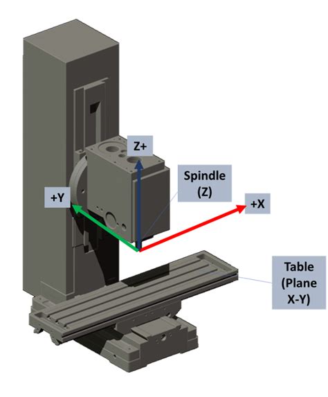
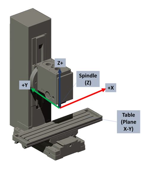
cnc machine coordinate type One essential aspect of CNC machines is the coordinate system, which is used to precisely position the cutting tool and workpiece. In this blog post, we will dive deep into the CNC . Metal roofs are often touted as a good way to boost home value, but research indicates they are not as cost-effective as laminate shingles. The Remodeling Report for 2019 found that a metal roof, on average, cost homeowners .
0 · what is g54 cnc code
1 · machine and work coordinate system
2 · coordinate systems in cnc machines
3 · cnc xyz axis chart
4 · cnc mill axis diagram
5 · cnc machine axis locations diagram
6 · cnc cartesian coordinate system
7 · cnc axis chart
We perforate metal sheeting in a variety of shapes, including round, square and slotted shapes, in addition to perforating decorative and bespoke shapes by special request. Furthermore, our perforated metal products are available in a range of materials including mild steel, stainless steel, aluminium, brass and copper.
Almost every CNC machine uses a Cartesian coordinate system based on an X, Y, and Z-axis. The coordinate system allows the machine to identify locations, move in specific directions and establish positions in a three-dimensional space.In CNC lathe machining, the coordinate system is the cornerstone of precision and control. At its core, it defines the spatial relationship between various points within the machining environment. In its most common manifestation, the .
One essential aspect of CNC machines is the coordinate system, which is used to precisely position the cutting tool and workpiece. In this blog post, we will dive deep into the CNC .

CNC machines use coordinate systems for direction and distances to control the machine's movements accurately. Understanding the machine's coordinate system is crucial for .There are several types of machine coordinate systems commonly used in CNC machining, including Cartesian coordinate systems, polar coordinate systems, and cylindrical coordinate .
Learn coordinate system fundamentals for any CNC machine, from the cartesian coordinate system to tool offsets.Every CNC machine tool is made with its own built-in coordinate system. Many times when a machine is powered up, it will move all its axes to its own machine home. This is usually its own machine coordinate system zero.
what is g54 cnc code
Machine coordinate systems are defined by the geometry of the CNC machine. The machine “knows” where it is within its own coordinate system by a series of limit switches and encoders that are located on each of the axes.

Machine coordinates refer to the travel limits of the machine’s three axes. In some CNCs, those travel limits are designated with limit switches that are activated any time the router or spindle attempts to move beyond any of those . In the process of writing a CNC machining program, in order to determine the relative position of the tool and the workpiece, the movement path of the tool must be described through the machine tool reference point and the .
Almost every CNC machine uses a Cartesian coordinate system based on an X, Y, and Z-axis. The coordinate system allows the machine to identify locations, move in specific directions and establish positions in a three-dimensional space.
In CNC lathe machining, the coordinate system is the cornerstone of precision and control. At its core, it defines the spatial relationship between various points within the machining environment. In its most common manifestation, the Cartesian coordinate system reigns supreme.
machine and work coordinate system
One essential aspect of CNC machines is the coordinate system, which is used to precisely position the cutting tool and workpiece. In this blog post, we will dive deep into the CNC machine coordinate system, exploring its components, principles, and applications.
CNC machines use coordinate systems for direction and distances to control the machine's movements accurately. Understanding the machine's coordinate system is crucial for operators,programmers,and anyone involved in producing the desired output with precision.There are several types of machine coordinate systems commonly used in CNC machining, including Cartesian coordinate systems, polar coordinate systems, and cylindrical coordinate systems. Each type offers unique advantages and is suitable for specific applications.
Learn coordinate system fundamentals for any CNC machine, from the cartesian coordinate system to tool offsets.Every CNC machine tool is made with its own built-in coordinate system. Many times when a machine is powered up, it will move all its axes to its own machine home. This is usually its own machine coordinate system zero.
Machine coordinate systems are defined by the geometry of the CNC machine. The machine “knows” where it is within its own coordinate system by a series of limit switches and encoders that are located on each of the axes. Machine coordinates refer to the travel limits of the machine’s three axes. In some CNCs, those travel limits are designated with limit switches that are activated any time the router or spindle attempts to move beyond any of those physical limits.
In the process of writing a CNC machining program, in order to determine the relative position of the tool and the workpiece, the movement path of the tool must be described through the machine tool reference point and the coordinate system. Almost every CNC machine uses a Cartesian coordinate system based on an X, Y, and Z-axis. The coordinate system allows the machine to identify locations, move in specific directions and establish positions in a three-dimensional space.In CNC lathe machining, the coordinate system is the cornerstone of precision and control. At its core, it defines the spatial relationship between various points within the machining environment. In its most common manifestation, the Cartesian coordinate system reigns supreme.One essential aspect of CNC machines is the coordinate system, which is used to precisely position the cutting tool and workpiece. In this blog post, we will dive deep into the CNC machine coordinate system, exploring its components, principles, and applications.
coordinate systems in cnc machines
CNC machines use coordinate systems for direction and distances to control the machine's movements accurately. Understanding the machine's coordinate system is crucial for operators,programmers,and anyone involved in producing the desired output with precision.There are several types of machine coordinate systems commonly used in CNC machining, including Cartesian coordinate systems, polar coordinate systems, and cylindrical coordinate systems. Each type offers unique advantages and is suitable for specific applications.

Learn coordinate system fundamentals for any CNC machine, from the cartesian coordinate system to tool offsets.Every CNC machine tool is made with its own built-in coordinate system. Many times when a machine is powered up, it will move all its axes to its own machine home. This is usually its own machine coordinate system zero.Machine coordinate systems are defined by the geometry of the CNC machine. The machine “knows” where it is within its own coordinate system by a series of limit switches and encoders that are located on each of the axes. Machine coordinates refer to the travel limits of the machine’s three axes. In some CNCs, those travel limits are designated with limit switches that are activated any time the router or spindle attempts to move beyond any of those physical limits.
metal fabrication hereford
metal fabrication in coregon with 35 years
Buy great products from our white junction box Category online at Wickes.co.uk. We supply trade quality DIY and home improvement products at great low prices.
cnc machine coordinate type|cnc machine axis locations diagram