cnc machine wiring diagram Learn how to effortlessly connect and configure your CNC machine with this ultimate guide on wiring and electronics. Whether you're a newbie or a pro, we've got you covered! Unveil the secrets of seamlessly setting up your .
Training in our newly expanded welding lab, you'll learn the fundamentals of welding and joining operations. In just four semesters, you'll get extensive hands-on experience with the four major types of welding. Dive into a cutting-edge program that prepares you to take the lead as a radiographic non-destructive test technician.
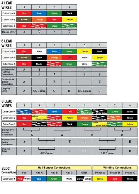
0 · stepper motor wire color chart
1 · cnc wiring diagram pdf
2 · cnc stepper motor wiring diagram
3 · cnc machine electrical wiring diagram
4 · cnc breakout board wiring diagram
5 · 8 wire motor wiring diagram
6 · 4 wire stepper motor diagram
7 · 4 wire stepper motor colors
Welding auto body sheet metal can present challenges for welders but Ron Covell is here to help mitigate warping with both MIG and TIG welding.
stepper motor wire color chart
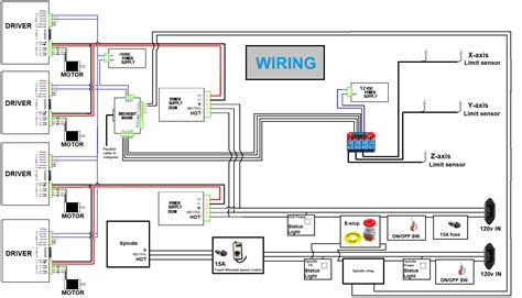
Educate readers on how to read and interpret a CNC machine electrical wiring diagram. Explain the symbols, notations, and color coding commonly used in wiring diagrams. Break down the .A well-designed CNC machine wiring diagram is essential for the successful installation and operation of a CNC machine. It should accurately depict the connections between the various electrical components, ensuring that the .
cnc wiring diagram pdf
A CNC machine wiring diagram is a documented blueprint detailing the electrical connections necessary to power a CNC machine. The diagram typically includes a connection point map with detailed diagrams of the .
The wiring diagram and circuit design for CNC machines play a crucial role in ensuring their optimal functioning and precision. This article will provide an overview of the key components and considerations when creating a wiring .
CNC Electronics and Wiring. This tutorial will make you an expert in wiring CNC electronics using a parallel breakout board and standard stepping motors and stepping motor drivers.
Learn how to effortlessly connect and configure your CNC machine with this ultimate guide on wiring and electronics. Whether you're a newbie or a pro, we've got you covered! Unveil the secrets of seamlessly setting up your .
The CNC machine electrical wiring is complete! This week I finished all the panel wiring for the Centroid Acorn - Dyna Myte 2800 CNC retrofit. This included adding circuit breakers to.Learn how to read and understand a CNC router wiring diagram to troubleshoot and repair electrical issues in your CNC machine.
Discover the correct wiring diagram for a Mach3 breakout board and ensure optimal performance for your CNC machine.
cnc stepper motor wiring diagram
Learn how to wire a CNC 3018 Pro machine with detailed diagrams and instructions. Get a step-by-step guide on connecting motors, limit switches, power supply, and other crucial .Next, we will provide you with a detailed wiring diagram specifically designed for the CNC 3018 Pro. This diagram will illustrate the proper connections between the various components, including the stepper motors, limit switches, power supply, and controller board. Following this diagram step-by-step will ensure that your CNC machine operates . The CNC machine electrical wiring is complete! This week I finished all the panel wiring for the Centroid Acorn - Dyna Myte 2800 CNC retrofit. This included.Explore detailed cable diagrams and pinout configurations for connecting various CNC machines, including Fanuc, Mazak, Siemens, and more. Comprehensive Guide to CNC Machine Cable Diagrams and Pinouts. Cable Diagrams and .

Common Issues and Troubleshooting Tips for CNC Wiring. CNC machines rely on well-functioning wiring systems to transmit electrical signals and power to various components. However, there are common issues that can arise with CNC wiring, causing problems with the machine’s performance. Here are some troubleshooting tips to help address these . A CNC wiring diagram is an essential document that outlines how the machine is wired together. It shows all the connections between components, such as motors, controllers, and drivers. This includes both electrical and electronic components, as well as physical components such as switches and connectors. Wiring Diagrams of CNC Electrical Systems CNC electrical diagrams are essential for keeping machinery running properly. They provide an overview of the electrical signals and connections that keep machines in sync and working at optimal levels. . Electrical Diagram Of The Cnc Machine Pinout Details Are Given In Scientific. 400w Spindle Wiring .
CNCPros sells premium replacement and OEM Fadal CNC machine parts from ATC clips to transmissions for Fadal CNC machines. Call Us: 208.855.9426. Currency: CNCPros.com - Done. . Wiring Diagrams . Wiring Diagrams. 4020 Service Files. Click on the links below to download a .pdf file. If you have more, please share!
If someone could help me out with the missing schematics (electrical wiring diagrams) for this CNC machine please, that would be really great. Any help would be very much appreciated. Thank you very much! 07-09-2022, 10:57 AM #2. gwood. View Profile View Forum Posts Private Message View Gallery Uploads Member Join Date Mar 2008
cnc control system electrical circuit diagram note: all functions may not be present or available as shown. refer to user manual. 11l1 device symbol component tag number (xx = number, yy = family) wire number corresponding to drawing component tag format wire label format xxyy scale sheet sizefscm nodrawing number rev standard mill electrical . I am getting ready to start the wiring of my DIY CNC Router and I am not sure what kind of wire I need to use/buy. Here is a list of my components. . The diagram in this video was a big help with understanding how everything connects but unfortunately it does not show wire specifics for all the connections. . When building/wiring a machine .Cnc Wiring Diagram - Free download as PDF File (.pdf), Text File (.txt) or view presentation slides online. This document provides a diagram of the wiring for a 5 axis CNC machine. It shows the power supply and distribution, as well as the wiring between the breakout board, driver boards, stepper motors and computer interface. Key components include a 120VAC power supply, . From controlling the motors for a 3D printer or CNC milling machine to creating a robotic arm, this wiring diagram gives you all the information you need to get the job done right. It also serves as a great starting point for more experienced makers who need to troubleshoot problems or make modifications to existing designs.
Creating a wiring diagram for your CNC machine is an essential part of the building process. By following these simple steps, you can create a professional-looking diagram that is easy to follow and will help ensure that your machine functions properly. Remember to select compatible components, label everything clearly, and test all connections .CNC Router Wiring Diagram. A CNC (Computer Numerical Control) router is a machine that uses computer-controlled motors to move a cutting tool along multiple axes to shape and cut various materials. The wiring diagram for a CNC router outlines the electrical connections required for the machine to function properly.
A CNC router wiring diagram is an essential guide for anyone wanting to understand how their router’s wiring functions. It identifies each component and how they work together to control the machine’s movements .We compiled all the official Fadal CNC Machine wiring diagram manual documentation and have added a few of our own. If you have more, share at [email protected]. The store will not work correctly when cookies are disabled. . Wiring Diagrams; Wiring Diagrams. Table_Of_Contents; Sec. 1 - Electrical_CE_Interlocks; Sec. 2 - Spindles; Sec. 3 - 4th .060409-1110 EST USA mikeh78: Assuming that HAAS has not changed the wiring, then it is simple, and you need to decide if you want hardware or software handshake. At the HAAS 25 pin end you need a male connector. And at the PC 9 pin end a female. At the HAAS end you can ignore pins 6, 8, and 20 because internally HAAS only jumpers these together.The Mach3 USB interface board is a widely used tool in the CNC machining industry. It allows for easy connection between a computer running the Mach3 software and various stepper motor drivers, enabling precise control of the CNC machine. The wiring diagram for the Mach3 USB interface board is relatively straightforward.
hikvision wall mount bracket with junction box
The CNC controller panel is located in front of the CNC machine and not shown on this CNC circuit diagram. The type of CNC servo drive shown on the diagram is 2 in 1 CNC servo drive which consists of servo drive and programming logic control section (PLC). The PLC section has some input and output (I/O).

CNC Machines Turn-Key Electronics 3D Resin Printers Resin Printer Parts Stepper Motors . Visit BuildYourCNC's page on the NEMA 23 motor to find the wiring diagram. We're going to use 4 terminals here, so we will not be using the center leads. We see the specification for the amps is 3.0 amps so we will need to set the driver at max amp capacity. Onefinity CNC Forum Onefinity Wiring Diagram . Direct connection to the stepper motor (without the inside wire) will damage your machine and cause the stepper to not operate. . Aftermarket cables should not be used and will void your warranty! Onefinity Wiring Diagram JPG 1046×809 137 KB. Wiring diagram 2.pdf (956.4 KB) 17 Likes. Z Stepper .
Download scientific diagram | Electrical diagram of the CNC Machine. * Pinout details are given in Figures 4 and 5. from publication: STEP-NC Compliant Intelligent CNC Milling Machine with an Open .
cnc machine electrical wiring diagram
Whether you’re a professional machine builder, hobbyist, or newcomer to the world of CNC machines, a detailed CNC router circuit diagram is an invaluable tool. By studying and following one, you’ll be able to confidently build—or modify—your own circuit boards and get your CNC machine up and running in no time. Circuit Diagram Of Cnc .Future Signal Inputs: The signal inputs on the CRP850-00E board are designed for NPN signals, which close signal to ground. The input signal terminals provide ports for direct wiring of limit switches, touch plate, and auxiliary signals. Replicated Outputs: These are 5V digital outputs which can be used to drive relays with 5V coils or 5V logic level devices.
cnc breakout board wiring diagram
Hi, i am working on Arduino controlled CNC machine. I'm not too good at understanding what goes behind the wiring of the controller with the motor drives, spindle, limit switches etc but have come up with a wiring diagram/schematic after watching other DIY CNC videos/builds, controlled via Arduino Uno. Teach Yourself About CNC Stepper Motor Wiring Diagrams. Computer Numerical Control (CNC) machining is a precise, automated process that allows engineers and precise precision in manufacturing. But to get the machinery up and running, you must first understand CNC stepper motor wiring diagrams. . Electrical Diagram Of The 3 Axis Cnc Milling .
8 wire motor wiring diagram
Motivational Welding Quotes #1 “Welding is not just about fusing metals; it’s about igniting your passion for creation.“ #2 “In the world of welding, sparks fly, but so do dreams.” #3 “A welder’s hands create what their mind envisions.” #4 .
cnc machine wiring diagram|cnc machine electrical wiring diagram